
|
|
|
Tormek DBS-22 Drill Bit Sharpener Modifications |

DBS- 22 Parts Breakdown
Image courtesy Tormek
Rick Krung noted on the Tormek Forum that he removed part of the tube on part #1 (where this jig attaches to the Tormek Universal Support Bar). This is the part highlighted in a red rectangle in the picture to the left.
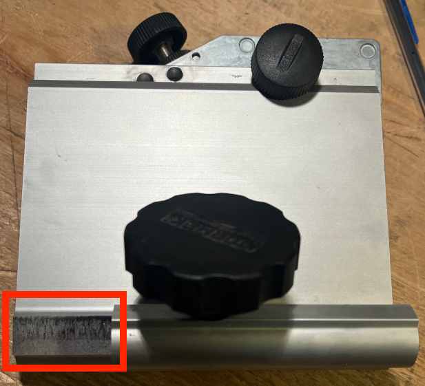
Modification to Part #1

40 mm Removed
This change allows the jig to be aligned further towards the center of the Tormek, making the side-to-side movement of the parts easier and more steady.
These modifications to the DBS-22 reference the parts breakdown shown to the right. Do be sure that they are appropriate for your DBS-22 jig. Tormek periodically makes modifications to their jigs, so the change may not work for your DBS-22.
I made that same change, removing 40mm as shown in the picture on the left.

I often use flat head screws which need to be counter-sunk by a bit which matches the screw head's angle. As noted in the picture to the left, 82° is a very common angle.
Such countersinks are available, but are expensive. Unfortunately, the DBS-22 will only sharpen bits down to 90°. Fortunately, I was able to modify my DBS-22 to make an 82° angle possible. The instructions for making such a modification are below.
Click on any of the pictures below to see a bigger version.

The pivot point on the compass is aligned with the hole for the DBS-22's pivot screw (part #9). 90° on the compass is aligned with 90° on the DBS-22's part #2. |

Note, this is 4° away from 90° as it is half the total angle. |

Notice how close the hole in the top of the picture is to the top edge of part #2. |

This needs to be in the path for the swing lock screw (part #7). This is noted in the picture to the right. On my jig, this hole needed to be 90mm from the left side, and 5mm from the top. If the hole is too far from the top, part #7 will interfere with part #1 when the jig is in use. |